
Part 2 - Fabrication.
The Watch Escapement Desk Toy is comprised of three sub-assemblies:
- Mainspring
- Gear Train
- Balance
As mentioned in Part 1 of this series, this design and the 3D printable STL files may be found on Thingiverse. All of the plastic parts were printed using PLA plastic on my Prusa MK3 3D printer.
Mainspring Sub-Assembly
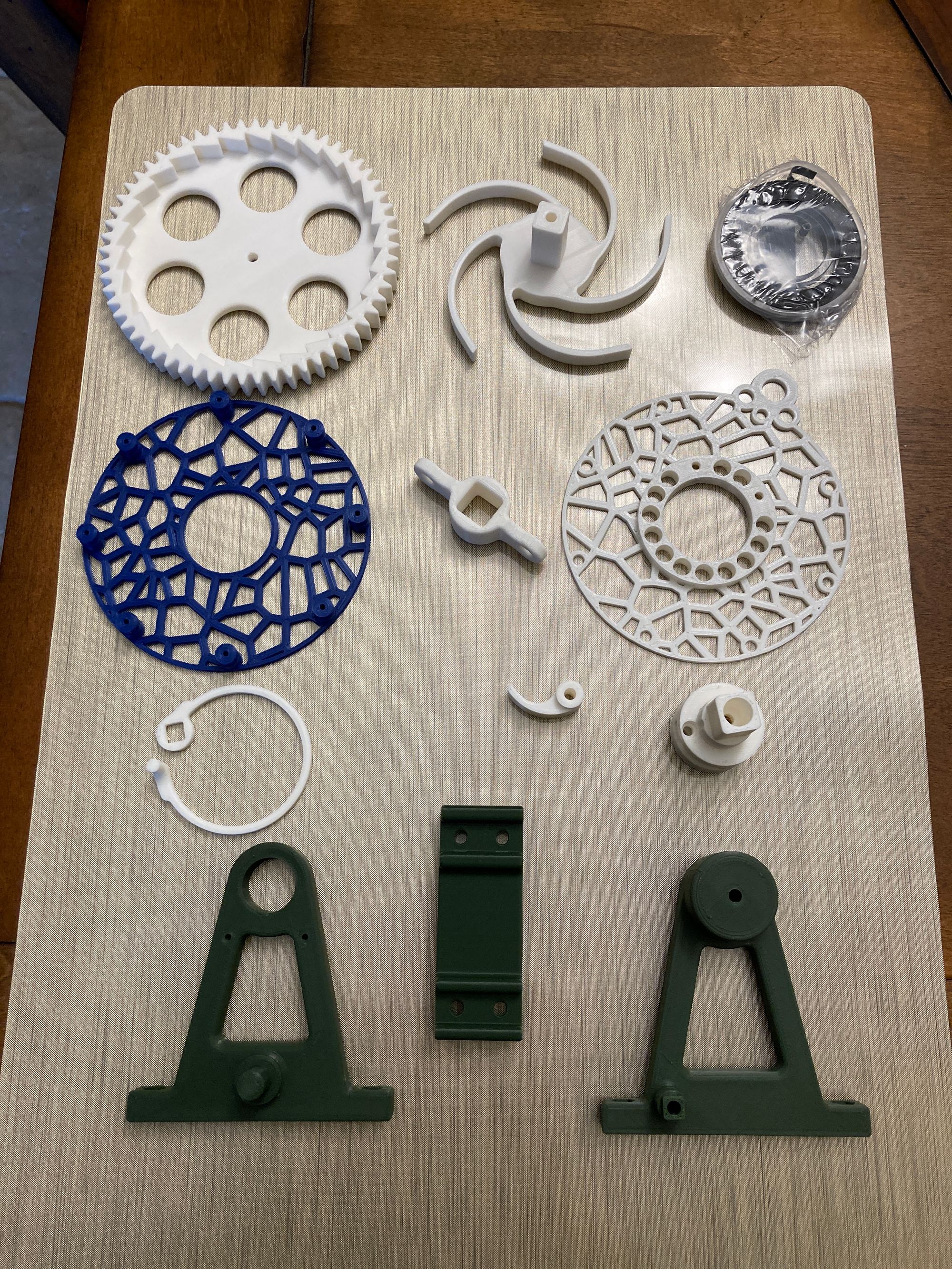
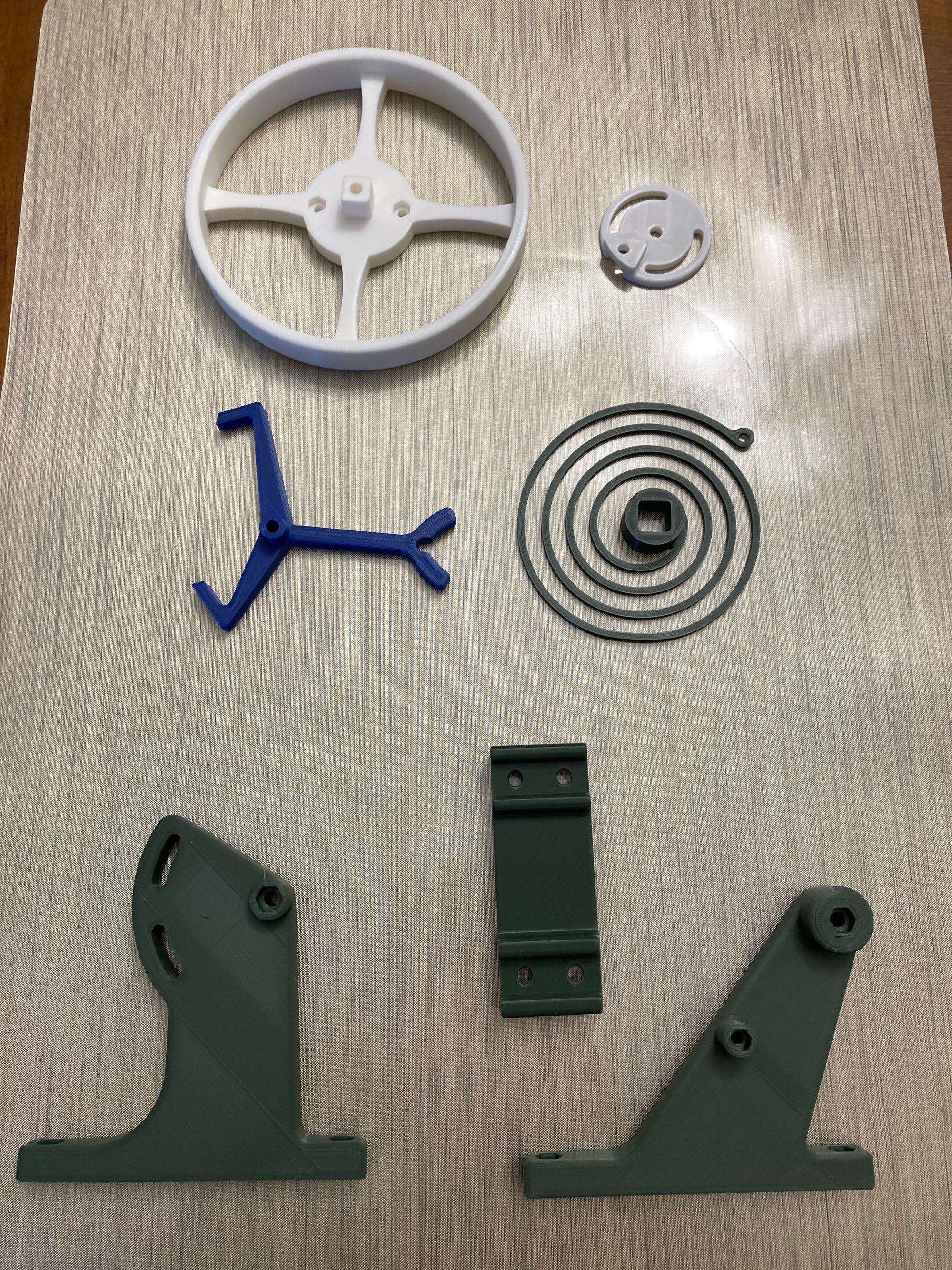
Not surprisingly, this sub-assembly holds the main spring, a winding knob and the largest gear of the mechanism. This design uses a steel spring which is normally used as the recoil spring in a chain saw rather than a plastic main spring used in the original design from which this one was adapted. Here is a photo of the plastic parts and the spring used in this sub-assembly.
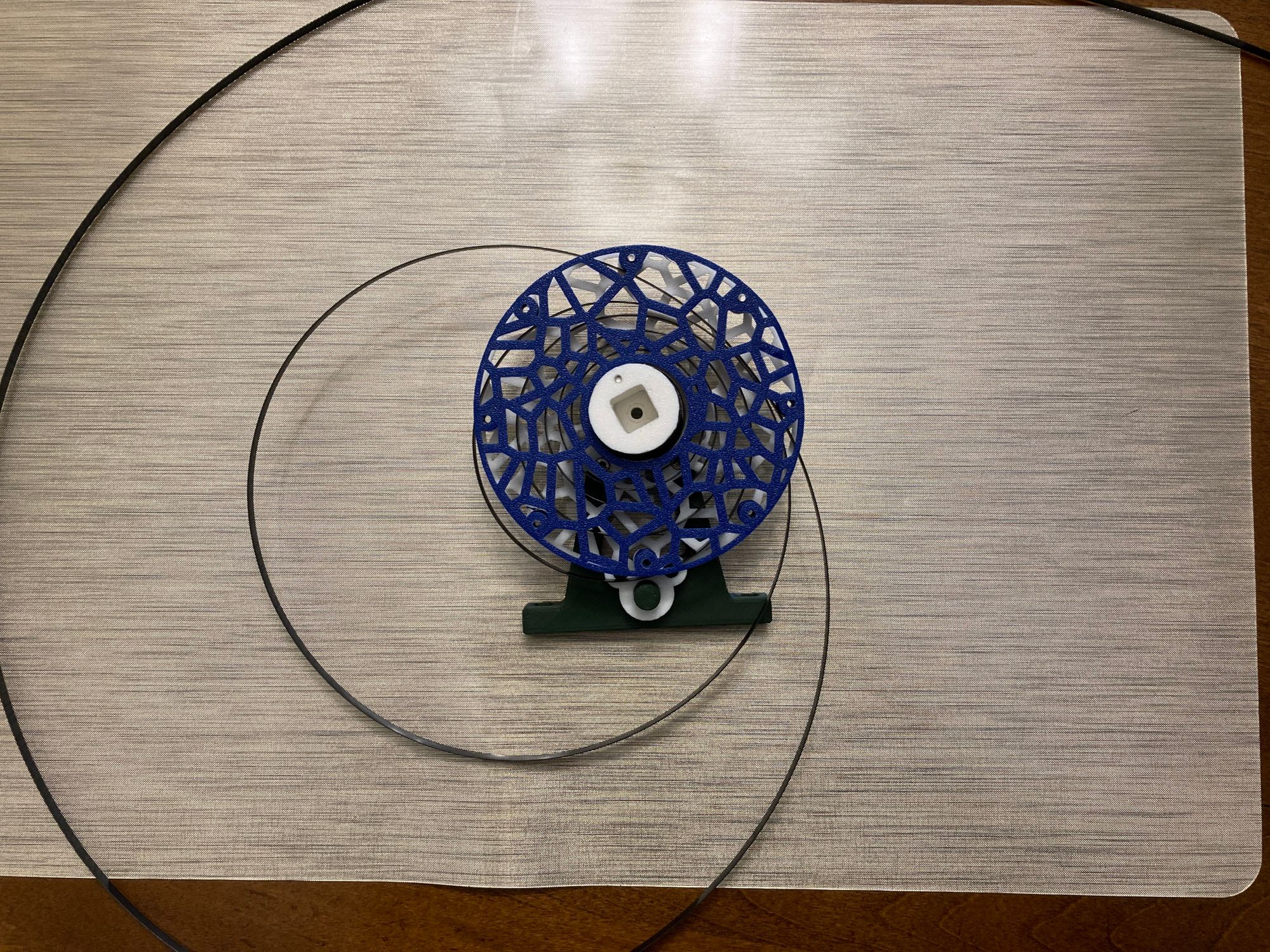
I found getting the steel spring inserted onto the sub-assembly to be the hardest part of the fabrication and the instructions given were not clear enough for me. What worked for me was to totally loosen the main spring, secure it to the reel, gradually screw together the spring retaining covers from top to bottom and then tightening the spring onto the reel. Hopefully a couple of pictures will help in clarifying this.
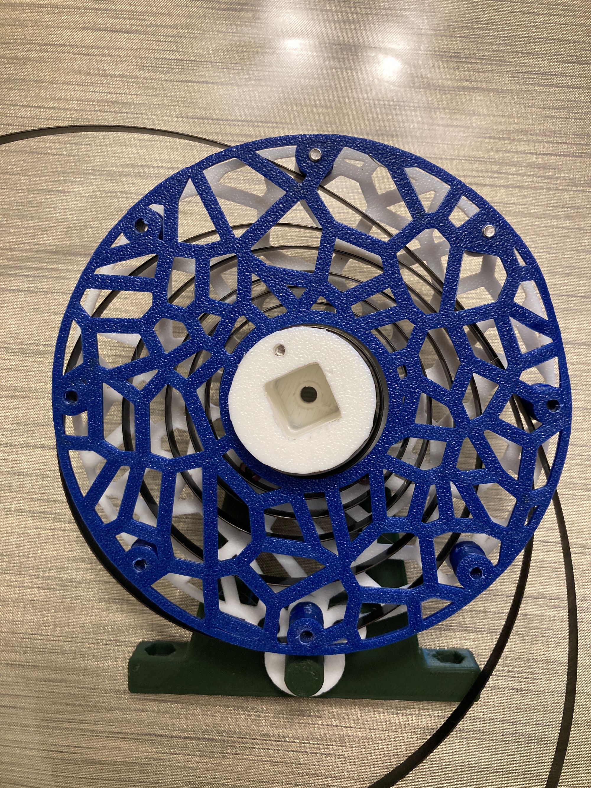
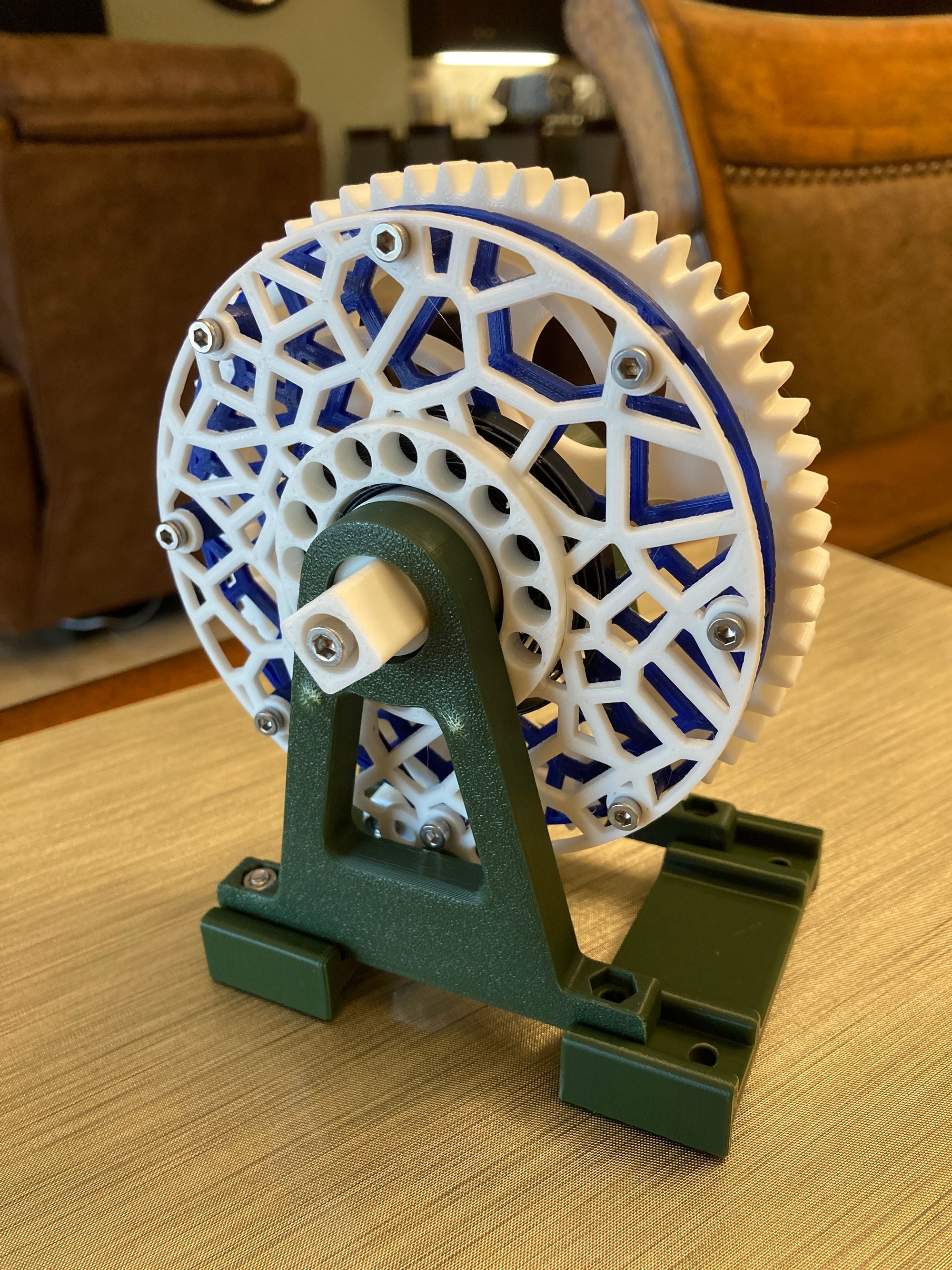
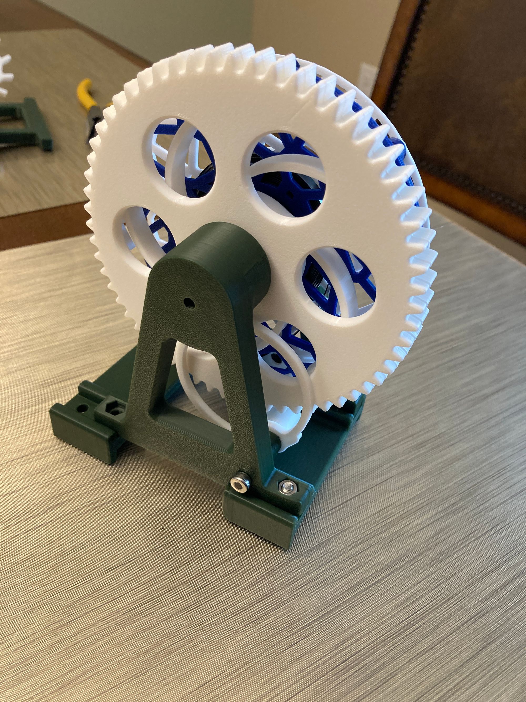
When fully assembled this sub-assembly looks like this:
Gear Train Sub-Assembly
The Gear Train sub-assembly uses a couple of gears to step up the rotational rate provided by the gear on the Mainspring Sub-Assembly. It's output gear directly drives the escapement wheel. Here is a photo of the plastic parts used in this sub-assembly.
When fully assembled this sub-assembly looks like this:
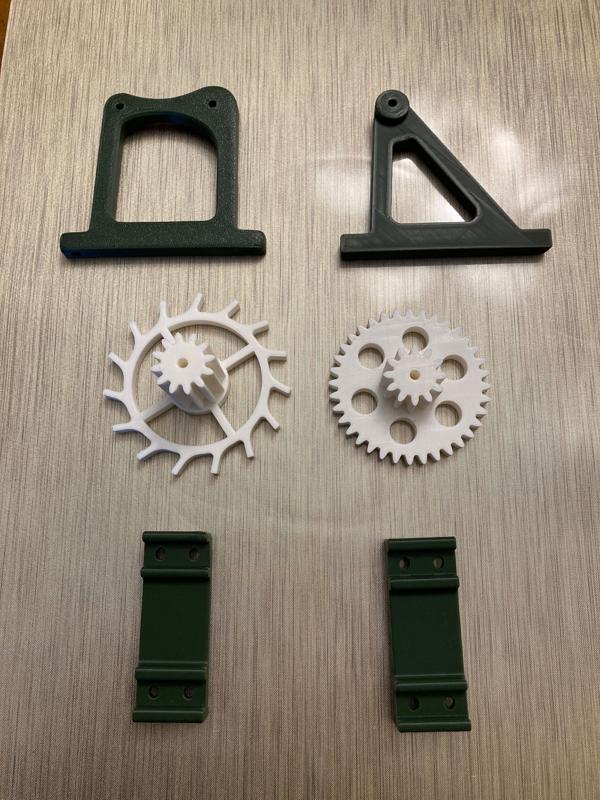
Balance Sub-Assembly
The Balance Sub-Assembly includes most of the escapement mechanism which allows the gradual release of the energy stored in the main spring which is then transmitted through the gear train and the escapement wheel to the balance wheel and its spring. The balance wheel rotationally oscillates alternately converting the balance wheel's motion to the winding of the spring and then the spring's unwinding to the balance wheel's motion. The fork connected to the balance wheel acts to release the energy through the escapement wheel in small bursts.
Here is a photo of the plastic parts used in this sub-assembly.
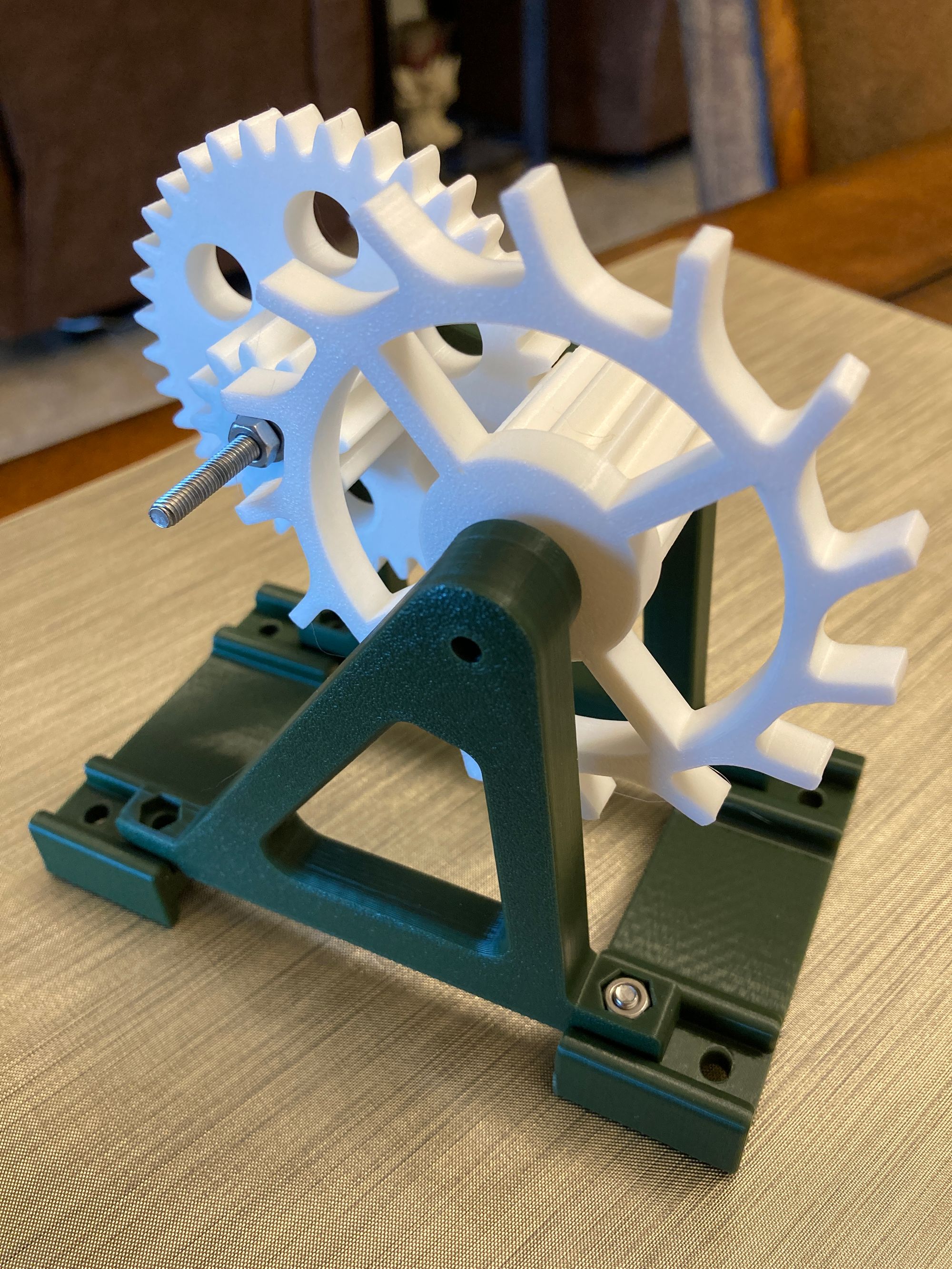
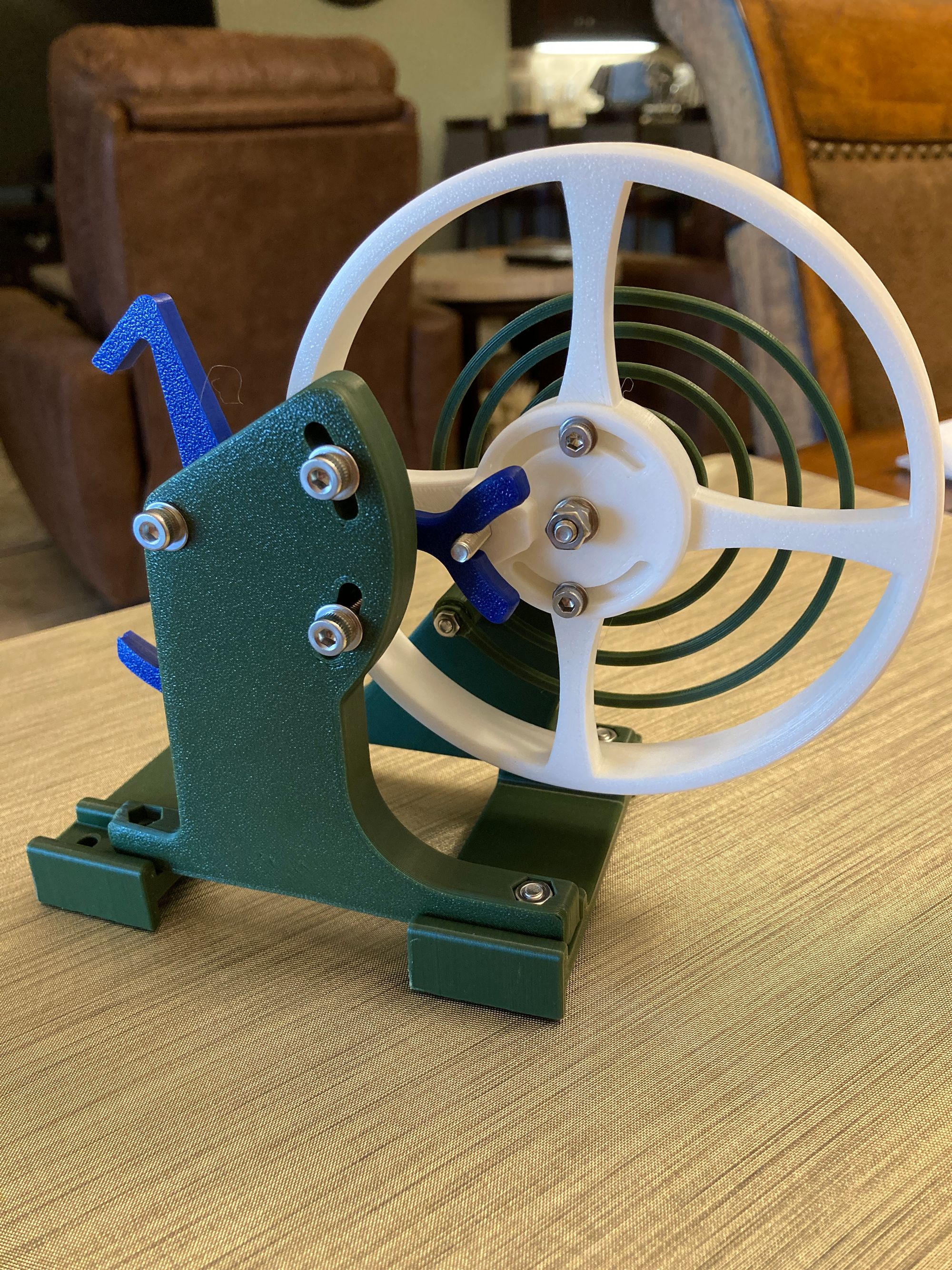
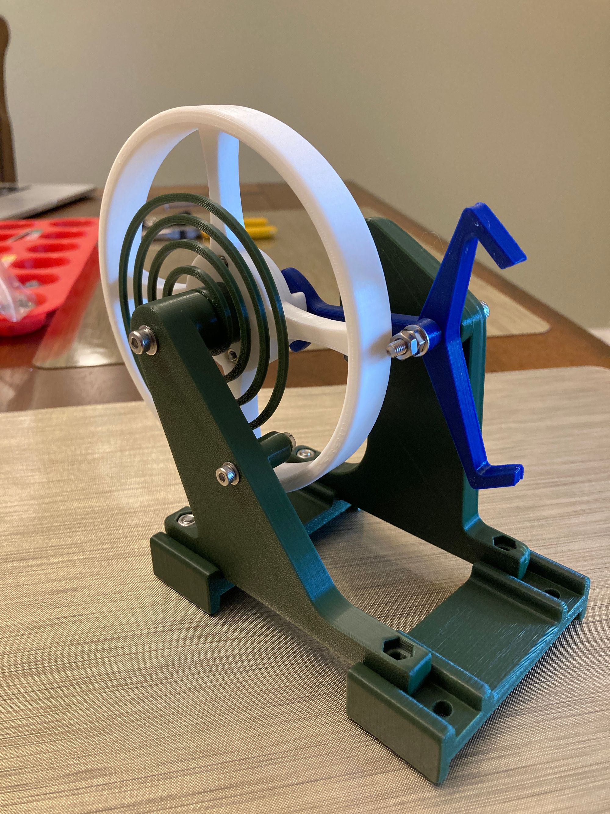
When fully assembled this sub-assembly looks like this:
Completed Assembly
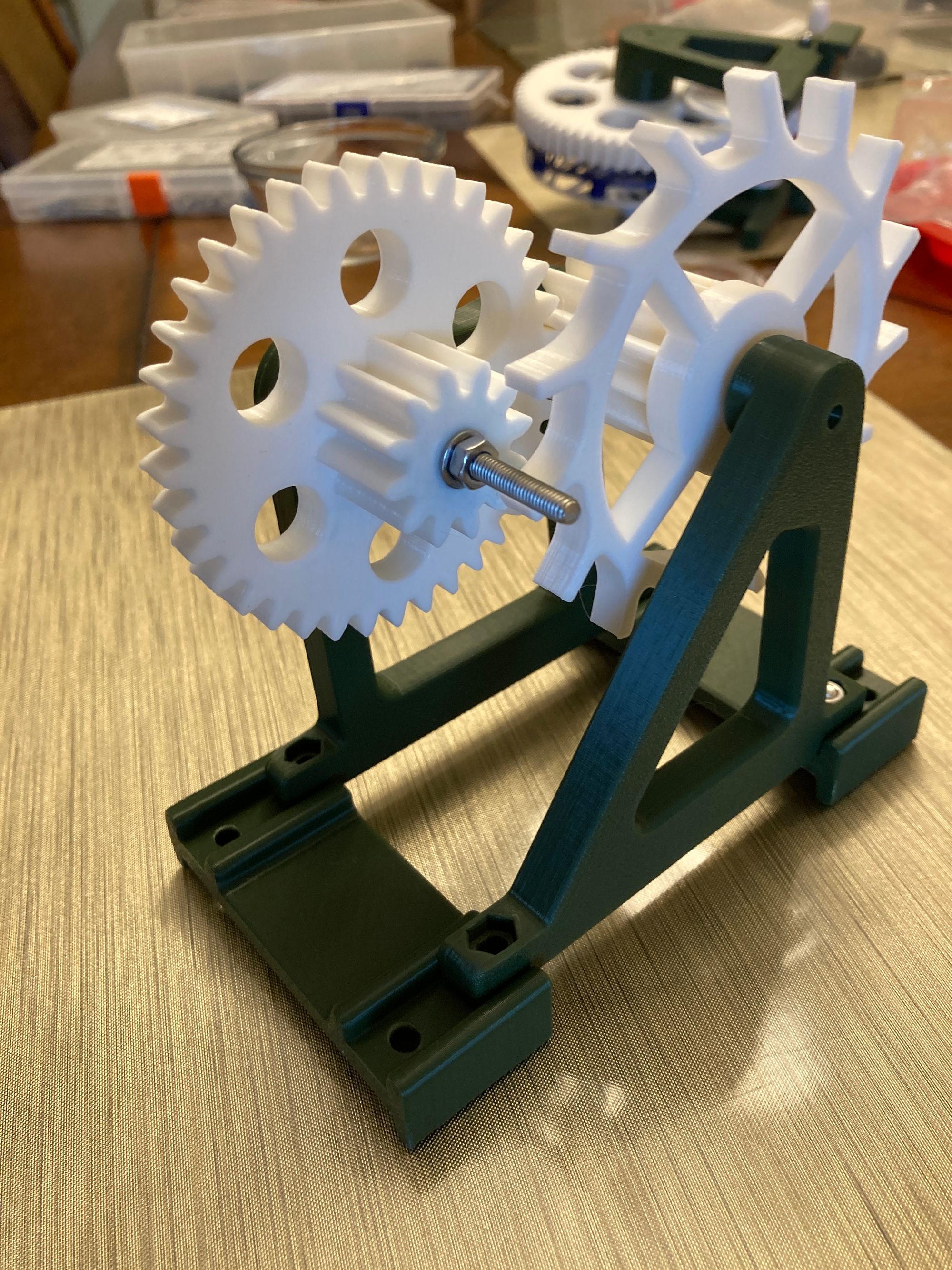
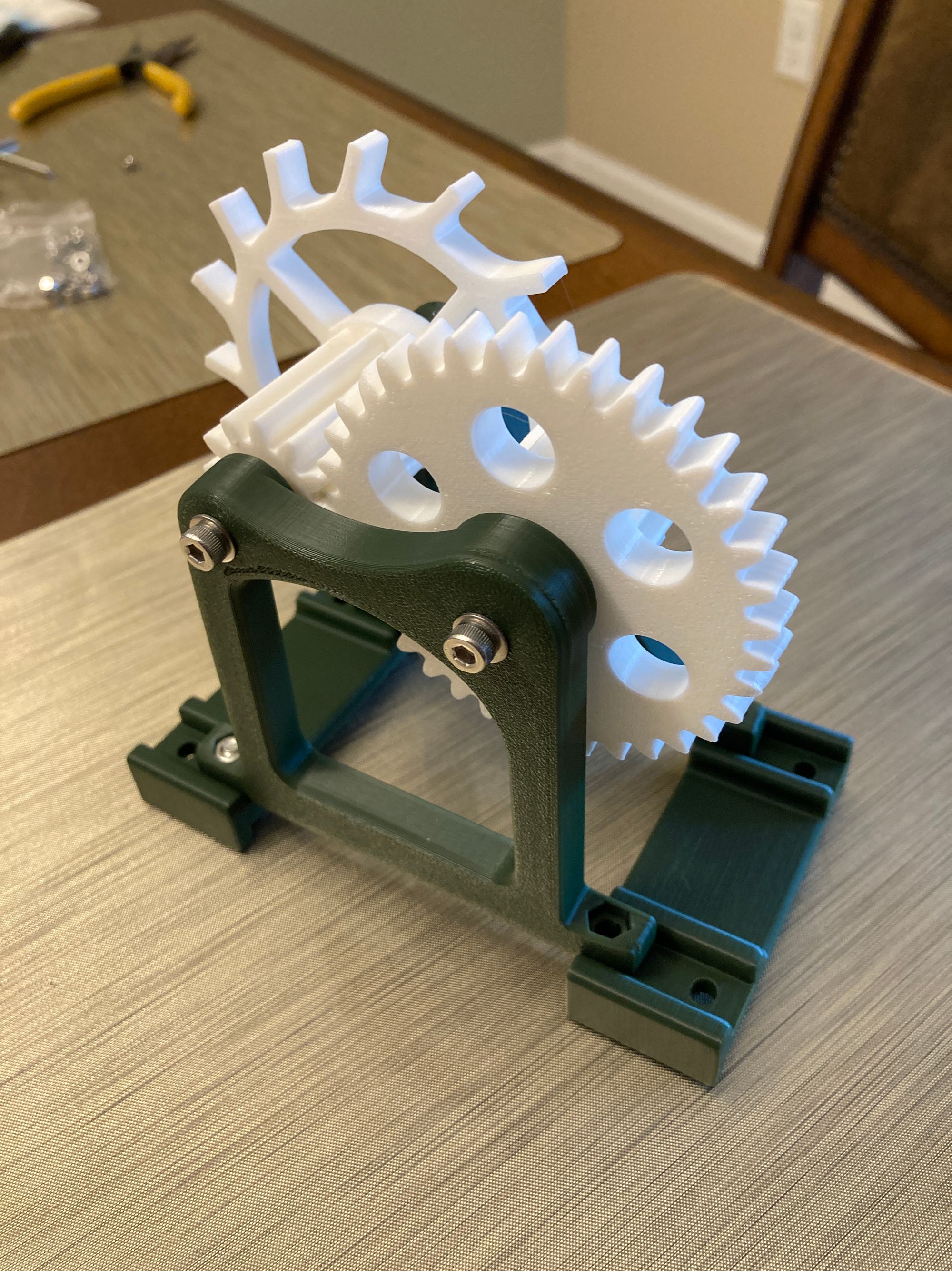
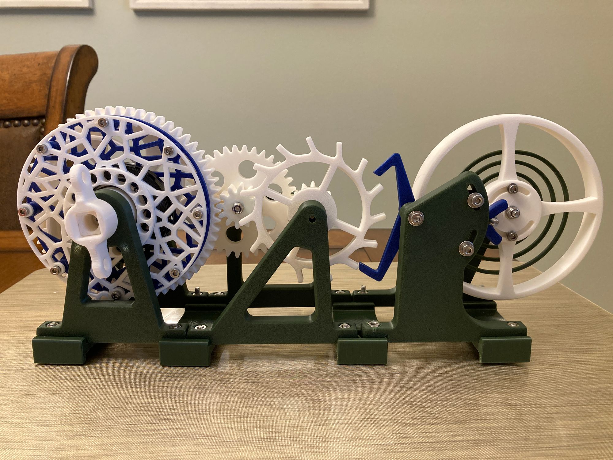
Joining together the sub-assemblies is as simple as engaging the gears and screwing together the parts. Here is a photo of the final assembly:
Operation
If well constructed, then getting the mechanism working is as simple as winding the main spring with the knob in a clockwise manner and then releasing it to allow the mechanism to operate freely.
In my case, it took a little bit of work adjusting the spacing between the Gear Train and Balance sub-assemblies to get the mechanism to work (you can see it working at the top of this post). It still does not work 100% reliably and I would not say that the operation is robust. I imagine I could spend some more time working to get it to work more robustly but I suspect that the design should also be improved to achieve a better mechanism.